As a professional repair technician, when a Universal H Series (UHS) heater fails to fire, it indicates a breakdown in the crucial sequence of operation, often triggered by a safety limit opening or a primary component failure within the gas or electrical ignition system.
Prior to attempting any diagnosis or repair, it is imperative to adhere to all safety protocols: Hazardous voltage can shock, burn, cause serious injury and or death. Only qualified technicians should remove panels or attempt repairs, and all power must be turned OFF before inspecting or replacing components.
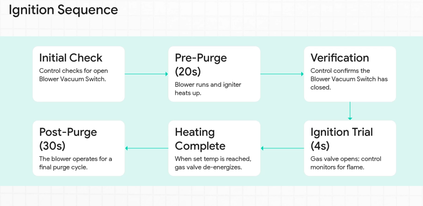
To understand why the heater will not fire, we first review the Normal Sequence of Operation:
- The control generates a call for heat (water temperature is 1° below the set point).
- The control checks for an open Blower Vacuum Switch (BVS).
- The Blower starts its 20-second pre-purge cycle, and the igniter begins heating.
- The control checks for a closed BVS.
- If BVS is closed and the igniter is hot, a 4-second trial for ignition begins (Gas valve opens, flame sense is monitored).
- If flame is sensed, the heater continues to operate, constantly monitoring safety components.
If the heater does not fire, the fault occurred during this sequence. Below are the primary diagnostic codes and generalized symptoms that indicate why ignition is being prevented or has failed:
I. Ignition Failure Codes
These codes appear when the heater attempted the ignition sequence but failed to establish a flame, resulting in a lockout.
| Code | Diagnosis | Troubleshooting Steps |
|---|---|---|
| IF | Ignition Failure | The heater failed its maximum number of ignition retries (3 times, then waits 60 minutes and retries 3 more times). Diagnosis Focus: Gas, flame sensing, or ICB failure. Troubleshooting: 1. Verify the main gas supply and the internal gas valve are ON. 2. Verify gas static and load pressures. Manifold pressure must be correct (1.8”–2.0” w.c. Natural Gas; 6.8”–7.0” w.c. Propane). Adjust manifold pressure if inlet pressure is correct. 3. Measure 22–28 VAC across the Gas Valve during the ignition trial. If voltage is present but there is no manifold pressure (use a manometer), replace the Gas Valve (FDXLGSV0001/2). If 22–28 VAC is not present, replace the ICB (FDXLICB1930). 4. Ensure the correct 5” Flame Sensor (IDXLFLS1930) is installed and securely fastened. Replace if damaged. 5. Inspect and/or clean burner tubes and orifices for blockage. |
| IO | Igniter Circuit Open | The control detected an open circuit at the igniter while the blower was running, causing lockout. Diagnosis Focus: Igniter component or wiring failure. Troubleshooting: 1. Power down and inspect igniter wiring, ensuring the plug is securely attached to the ICB. 2. Measure Igniter (FDXLIGN1930) resistance (must be 8–25 ohms between 20°–140°F). If out of range, replace the igniter. 3. If resistance is correct, replace the ICB. |
| HF | Flame present with Gas Valve not energized | Flame is sensed when the gas valve is off, meaning the control safety failed. Diagnosis Focus: Gas valve leakage or ICB flame monitoring error. Troubleshooting: 1. Power cycle the heater. 2. If the error reappears, call for heat and test for 24VAC off the Gas Valve. 3. If 24VAC is present and flame is present, but the valve should be off, replace the Gas Valve (FDXLGSV0001/2). 4. If flame is not present (check sight glass), or if the voltage checks are inconclusive, replace the ICB (FDXLICB1930). |
II. Pre-Ignition Safety Lockout Codes
These codes prevent the ignition sequence from proceeding because a critical safety loop is open or a required air/water flow condition is not met.
| Code | Diagnosis | Troubleshooting Steps |
|---|---|---|
| LO | Limit Open | The safety limit string is open (Water Pressure Switch, High Limits, Vent Pressure Switch, etc.). Diagnosis Focus: Water flow, plumbing issues, or limit switch failure. Troubleshooting: 1. Water Flow: Verify pump is running and flow is adequate (check minimum GPM requirements). Low flow can cause high limits to trip. 2. Water Pressure Switch (WPS): Test continuity across WPS terminals while the pump is running (should be closed). If open, replace WPS (FDXLWPS1930) or adjust if the heater is above/below the water level. 3. High Limits: Inspect and test continuity across the Temperature Limit Switches (FDXLHLI1930). If open, replace the switch(s). 4. Indoor Installation: Inspect Vent Pressure Switch (FDXLVPS1930) tubing and connections (IDXL2SNT1930). Ensure flue is not blocked or restricted. Test continuity across VPS terminals; if open, replace the switch. 5. Newer Heaters (Post Feb 2016): Test continuity across the Exhaust Gas Limit Switch (FDXLEGL1931). If open, it is a one-time safety and requires replacement and inspection of the heat exchanger. |
| AO | Blower Vacuum Switch open | The BVS did not close after the blower started, preventing the transition to ignition. Diagnosis Focus: Blower power, BVS, or vacuum line issue. Troubleshooting: 1. Check for damaged blower/BVS wiring or damaged vacuum tubing. 2. Measure Blower (FDXLBWR1930) resistance (4–5 ohms post-Sept 2010; 8–9 ohms prior). If out of range, replace the blower. 3. If calling for heat and the blower runs, verify 110–125 VAC at Inducer off ICB. If voltage is present, replace BVS (FDXLBVS1930). If voltage is absent, replace the ICB. |
| AC | Blower Vacuum Switch closed | The BVS is closed when it should be open, stopping the blower from starting the pre-purge cycle. Diagnosis Focus: Stuck switch or defective ICB control. Troubleshooting: 1. Isolate the BVS (FDXLBVS1930) and test continuity. If continuity exists (closed), replace the switch. 2. If the blower runs continuously while the heater is in STANDBY mode, replace the ICB (FDXLICB1930). |
III. Power and Board Failure Codes/Symptoms
If the heater does not display a code or fails due to fundamental electrical faults, it cannot initiate the firing sequence.
| Symptom / Code | Diagnosis | Troubleshooting Steps |
|---|---|---|
| No Power / Blank Display | Fuse open, incorrect voltage selection, or component failure (Transformer, ICB, Fuse Board). | Follow the "Heater Will Not Power Up" flow chart: 1. Incoming Power: Verify correct supply voltage (110–125 VAC or 220–245 VAC) at TB1 terminal block. 2. Selector Plug: Ensure the Voltage Selector Plug (P2) matches the incoming voltage. 3. Fuses: Check FC1 & FC2 (3A slo-blo) for continuity. If open, check transformer wiring/resistance. 4. Transformer: Test output (P4) for 22–28 VAC (low voltage, pins 1 & 2) and 110–125 VAC (high voltage, pins 4 & 6). Replace Transformer (IDXL2TRF1930) if incorrect. 5. ICB Fuses: Check F1 fuse (3A blade style) on the ICB. If blown, check low voltage safety components (Gas Valve, WPS, limits) for shorts. 6. ICB Output: Verify 22–28 VAC between AC & COM terminals on the ICB. If present but display is blank, replace Display/Keypad. If absent, replace ICB (FDXLICB1930). |
| PF | Voltage Polarity Reversed, Low Voltage Detected | The incoming electrical supply has polarity issues, low voltage, or poor grounding. Troubleshooting: 1. Verify incoming power is within 10% +/– of required voltage. 2. Inspect ground and neutral connections (internal/external) for cleanliness and security. 3. If checks are acceptable, replace the ICB (FDXLICB1930). |
| EE | EEPROM Error / Bad Board | Internal error detected in the ignition control board. Troubleshooting: Replace ICB (FDXLICB1930). |
Key Non-Firing Condition: Sensor Failure (SF or HS)
A heater may fail to fire because the control believes the water temperature is already too high or if the sensors are providing conflicting data, preventing a call for heat.
- SF (Sensor Failure): Thermistor is reading out of range, or the two sensors differ by 5°F or more.
- Troubleshooting: Ohm the thermistor (FDXLTER1930) between the black wire and each red wire (readings should be the same, 10k ohms at 77°F). If readings differ significantly (more than 1°), replace the thermistor; otherwise, replace the ICB.
- HS (High Sense): Water temperature exceeded 104°F, or the sensor detected a rapid rise (6°F in 60 seconds), indicating potentially low flow.
- Troubleshooting: Verify water flow is adequate. Check plumbing to ensure the inlet and outlet are not reversed, as this frequently causes the error. Compare the heater's reading to an accurate thermometer. If the thermistor checks out, replace the ICB.